
Motor Generator Kit
KITMG
Introduction
This page contains instructions for constructing a motor-generator system and using it for science experiments. All information is based on the materials that come in the MiniScience Motor Generator Kit. If you don't have this kit, you can order one online.
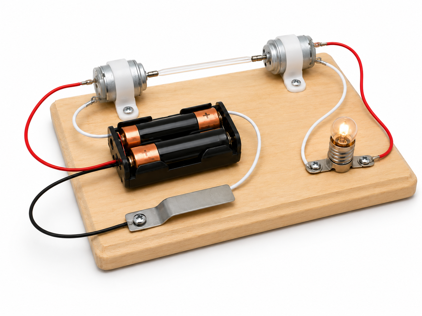
In this project you will make two simple electric circuits: one involving a motor that operates with batteries, and the other involving a generator that produces enough electricity to light up a light bulb. The mechanical power to run the generator comes from the motor on the other circuit. The transmission of mechanical force from the motor to the generator is achieved using a plastic tube.
On one side you will convert electrical energy to mechanical energy. On the other side you will convert mechanical energy to electrical energy. Really cool. Read below for details.
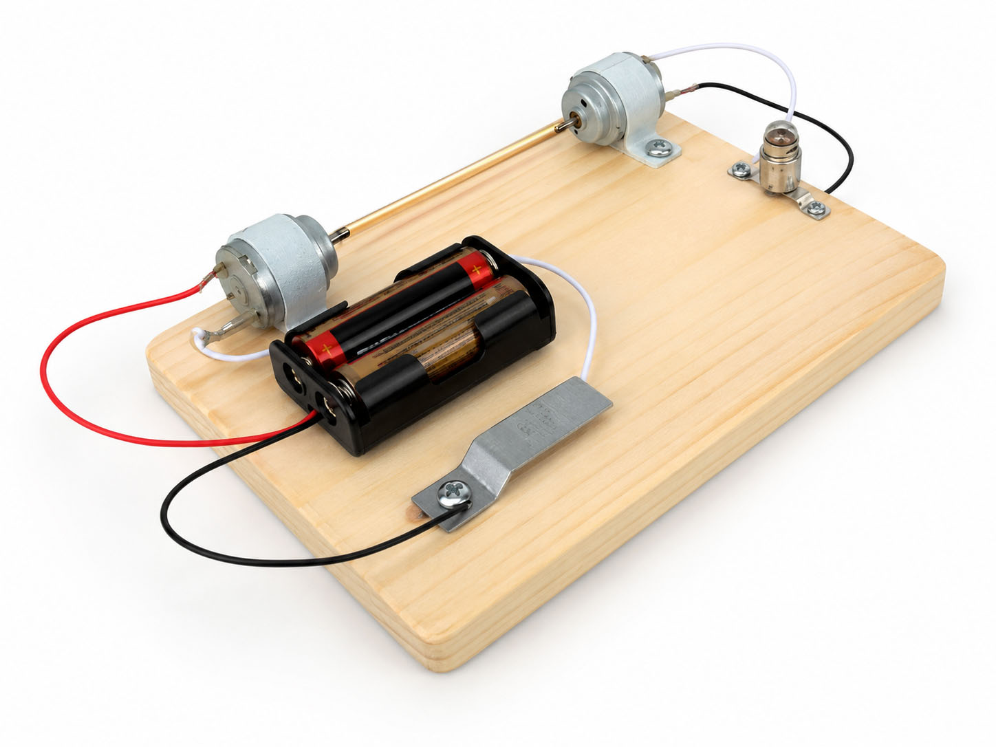
With this project students can explore:
- Simple electric circuits and the basic concepts of electricity and electrical circuits.
- Using electricity to run mechanical devices such as electric fans, drills, and mixers.
- Production of electricity using mechanical energy, such as water turbines in dams that are connected to electrical generators.
- Using tools to assemble the circuit and using a multimeter to measure the voltage.
Items Needed
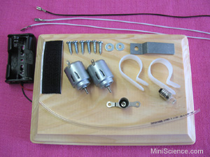
The Motor Generator Kit usually comes with parts ready to use. The picture below shows the materials found in a Motor Generator Kit from MiniScience.
Materials Checklist
Before using the kit, verify the content with the parts in this picture.
- Two electric motor/generators
- One basic lamp holder
- One miniature lamp
- One wooden board
- One simple switch (push plate)
- Motor/generator connecting tube
- Two plastic motor mounts
- Ten metal screws
- Four metal washers
- Three connection wires
- One 2×AA battery holder
- Interlock tape (pair, 2")
Requires 2 AA batteries (not included).
A Science Fair Project
The electric motor generator kit may be used for a science project, technology project, display project, or an engineering project for your science fair. Your completed project will also be an educational tool for yourself and your classmates who need to understand simple electric circuits, the production of electricity, and the conversion of energy.
Assembly Procedure
- Mount two motor-generators on one side of the wooden block, faced to each other about 8 centimeters (3 1/4 inches) apart.
- Cut a length of plastic tube long enough to connect both shafts together while being straight and covering both shafts.
- Mount the lamp holder using two screws on the right, near one motor/generator.
- Mount the battery holder (using two screws or hook and loop tape) on the left, near the other motor generator.
- Use two connector cables to connect the metal contacts of the motor/generator on the right to the two screws of the lamp-holder.
- Connect the black wire of the battery holder directly to one of the metal contacts of the motor on the left.
- Mount 2 screws near the battery holder about 3 centimeters (1 1/2") apart. These two screws will form a switch, so one of them will hold the switch plate.
- Connect the red wire of the battery holder to one of the screws of the switch.
- Connect the other screw of the switch to the remaining contact of the motor/generator on the left.
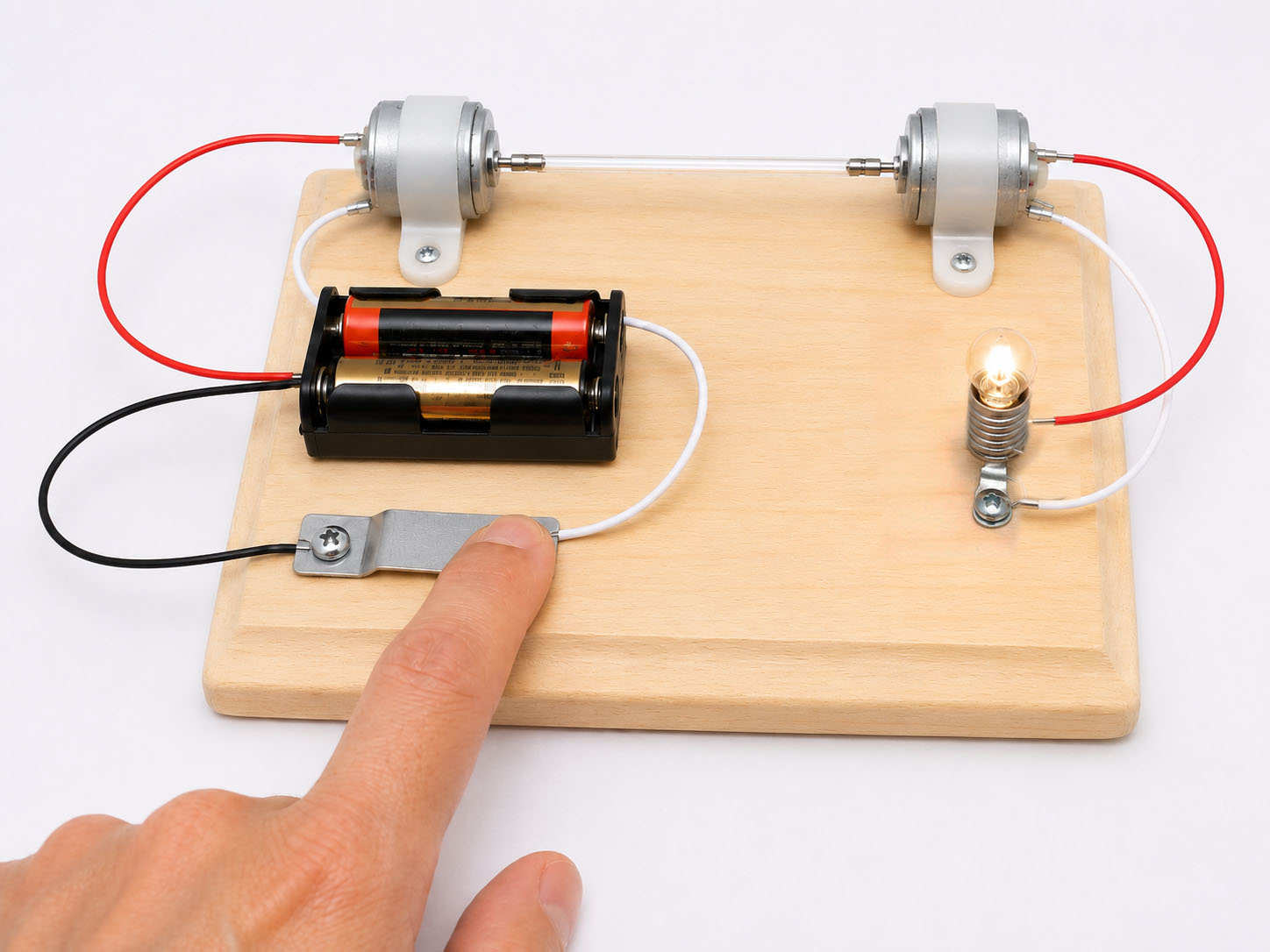
Now your motor/generator system is ready for test. Insert the batteries, screw a lamp into the lampholder, and then push the switch to close the circuit on the left. The generator on the right will turn on the light bulb.
What Is Happening?
The motor/generator on the left works as a motor. The turning shaft of the motor transfers the mechanical energy to the connecting tube and to the motor/generator on the right, which acts as a generator. The generator produces electricity that lights up the light bulb.
Get Ready for Scientific Observations
Before you continue with the observation and reporting, you must learn how to use your multimeter to measure the electrical voltage between two points. Understand the difference between DC voltage and AC voltage.
Science Project
Research question: How does the voltage change in a motor/generator circuit?
Sample hypothesis 1: I hypothesize that the voltage does not change in different parts of a motor/generator circuit.
Sample hypothesis 2: I hypothesize that the voltage on the motor side is more than the voltage on the generator side.
Experiment (Observation and Reporting)
- Connect the probes of the multimeter to the wires coming out of the battery holder. Read and record the DC voltage while the motor is not running.
- Push the button (close the switch) and repeat your measurement while the motor is running.
- Connect the probes of the multimeter to the metal contacts of the generator and measure the AC voltage while the generator is running and the lamp is turned on.
- Open the circuit by unscrewing the lamp, then connect the probes of the multimeter to the metal contacts of the generator and measure the AC voltage while the generator is running.
Record your readings in the table below:
| DC Voltage (battery / motor side) | AC Voltage (generator side) | |
|---|---|---|
| Closed Circuit | ||
| Open Circuit |
Sample data table (Values are not real):
| DC Voltage (battery / motor side) | AC Voltage (generator side) | |
|---|---|---|
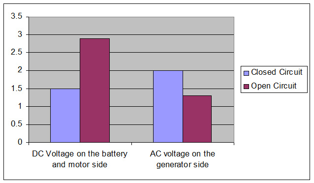
| Closed Circuit | 1.5 | 2 |
| Open Circuit | 2.9 | 1.3 |
Analysis and Reporting
Review the voltage readings you recorded in the data table and discuss why the voltage is different in a closed circuit and in an open circuit. Also discuss why the electrical voltage produced by the generator is different from the voltage produced by the batteries.
Make a Graph
Use your data/results table to draw a graph, or create one like this in Excel. Make one bar for each measurement so you can visually compare the voltage on the motor side and the generator side, in closed and open circuits.
If you do not have this kit, you can order it now. Check price and availability at the secure online store.
Secure Online Store
Order Now
Motor Generator Kit — Part# KITMG
Product URL:
https://shop.miniscience.com/KITMG
MiniScience.com
1059 Main Avenue
Clifton, New Jersey 07011
Tel: (973) 777-3113
Email: info@MiniScience.com