
Electric Bell Kit
BELLKIT
Introduction
This page contains instructions for assembling a working electric bell circuit and using it to learn about electromagnetism. The electromagnetic electric bell (often called a trembler bell) itself comes ready-made. Your job is to connect it into a series circuit with the knife switch and the battery holder so it rings. All information is based on the materials that come in the MiniScience Electric Bell Kit. If you don't have this kit, you can order one online.
In this project you build a simple series circuit made of an electric bell, a knife switch, and a battery holder. When you close the switch, current flows through the coil and turns it into an electromagnet. The electromagnet pulls a metal striker arm so it hits the gong.
As the arm moves, it breaks its own contact, the electromagnet releases, and a spring pulls the arm back, which closes the contact again. This make-and-break cycle repeats many times per second, so the bell rings continuously. Really cool. Read below for details.
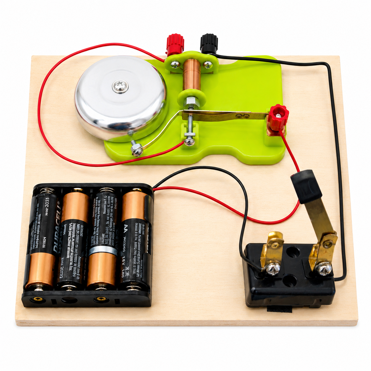
With this project students can explore:
- Simple electric circuits and the basic concepts of electricity and electrical circuits.
- How electricity creates magnetism (electromagnets) and how that magnetism does mechanical work.
- How everyday devices such as doorbells, buzzers, and relays use a make-and-break electromagnet.
- Using simple tools to assemble a circuit and connect components safely with terminals.
Items Needed
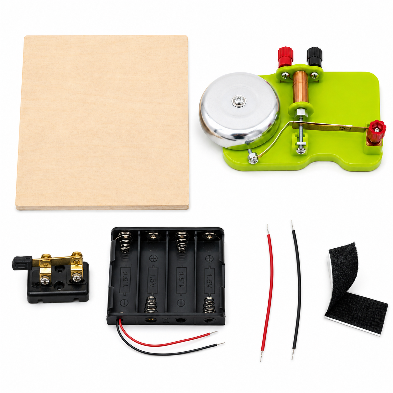
The Electric Bell Kit usually comes with parts ready to use. The picture below shows the materials found in an Electric Bell Kit from MiniScience.
Materials Checklist
Before using the kit, verify the content with the parts in this picture.
- One electric bell
- One knife switch
- One battery holder with pre-installed red and black wires
- Two additional wires (red or black, assorted)
- One wooden base
- Self-adhesive hook-and-loop (Velcro) tape for mounting
Requires 4 AA batteries, 1.5 V each (not included).
A Science Fair Project
The electric bell kit may be used for a science project, technology project, display project, or an engineering project for your science fair. Your completed project will also be an educational tool for yourself and your classmates who need to understand simple electric circuits, electromagnetism, and how an electromagnet can be used to do mechanical work.
Before You Start
Do not install the batteries until all connections are complete.
Locate and identify the following connection points. You will use each of them exactly once.
| # | Connection point | Location |
|---|---|---|
| 1 | Red binding post | Top of the bell base |
| 2 | Black binding post | Top of the bell base |
| 3 | Red side terminal | Right side of the bell mechanism |
| 4 | Bottom contact screw | Below the metal striker arm |
| 5 | Red wire | Pre-installed on the battery holder |
| 6 | Black wire | Pre-installed on the battery holder |
| 7–8 | Two metal terminals | On the knife switch |
Assembly Procedure
Step 1 - Lay Out the Components
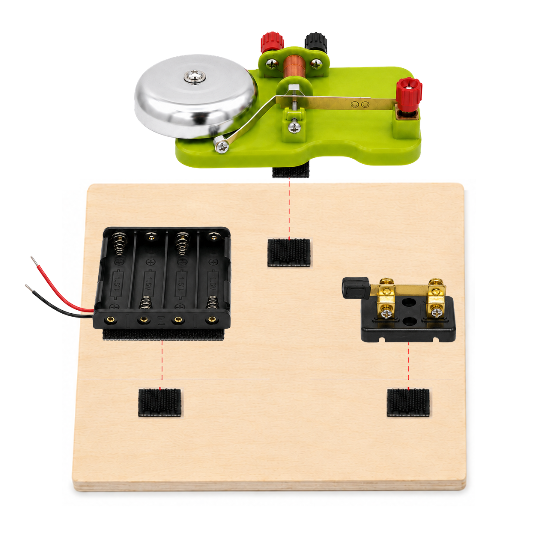
Place the components on the wooden base in this arrangement:
- Bell: top area
- Battery holder: bottom left
- Knife switch: bottom right
Before mounting anything, confirm that every wire reaches its terminal without being pulled tight. Leave a little slack.
Step 2 - Mount the Components
- Cut the self-adhesive Velcro tape into pieces sized for each component.
- Stick one side of each piece to the wooden base and the matching side to the underside of the bell, the battery holder, and the knife switch.
- Press each component firmly onto the base.
Important: Keep the tape clear of all terminals, screws, and the moving parts of the knife switch.
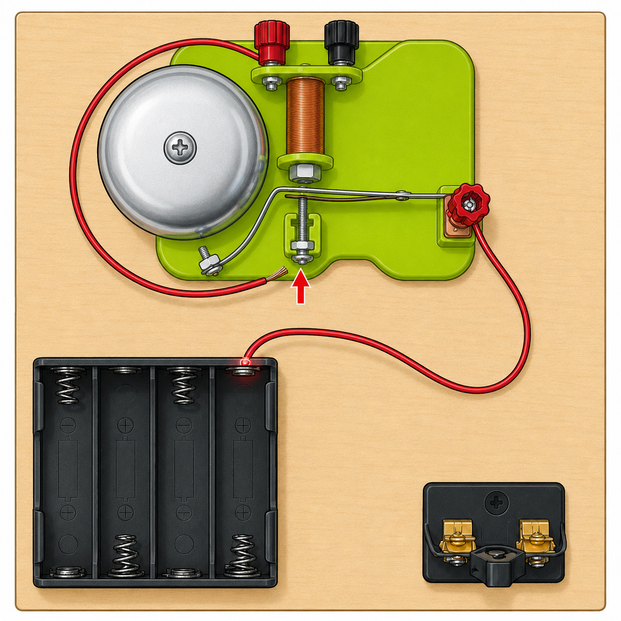
Step 3 - Battery Holder Red Wire → Bell Side Terminal
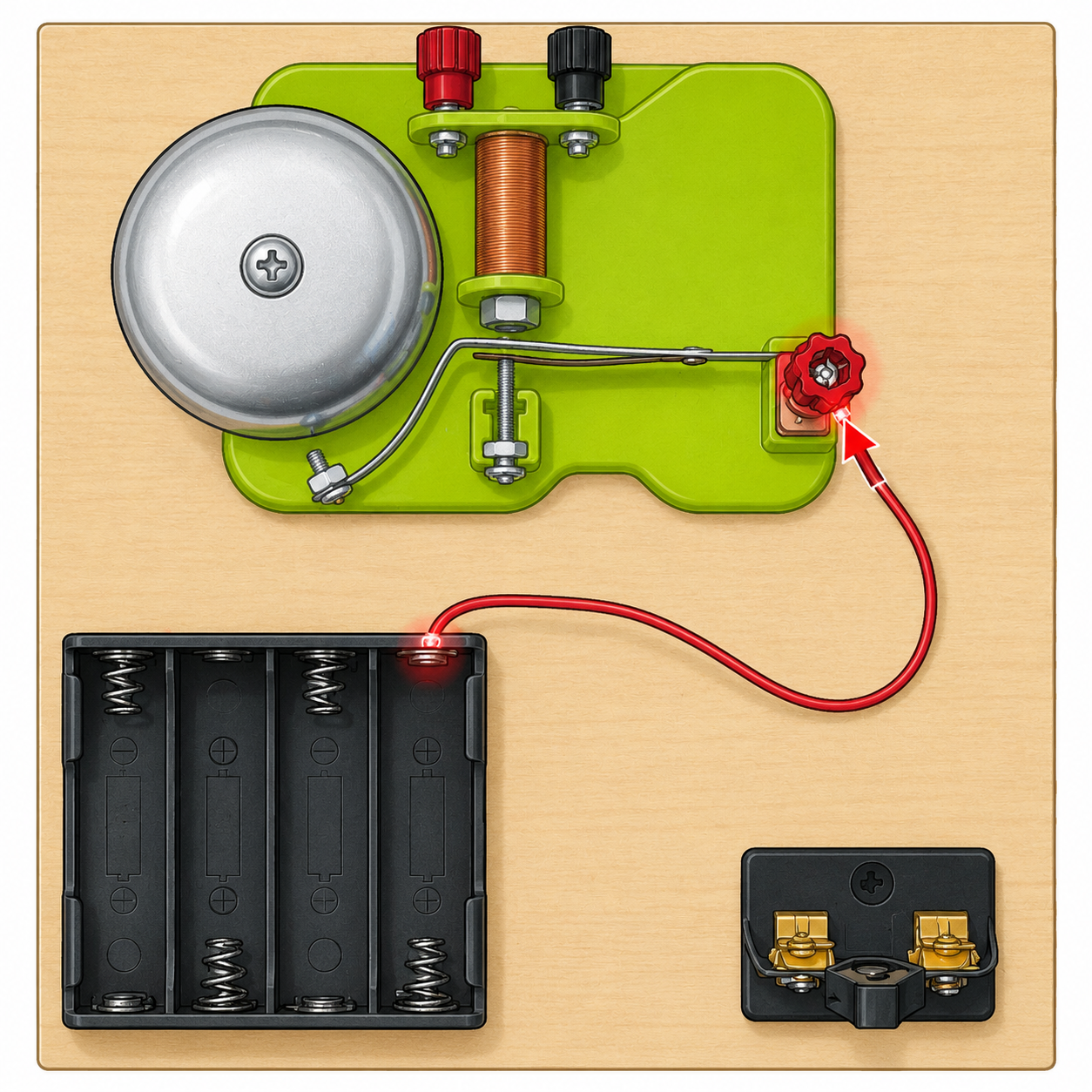
- Take the red wire pre-installed on the battery holder.
- Loosen the red side terminal on the right side of the bell mechanism.
- Insert the bare metal end of the wire and retighten the terminal.
Step 4 - Red Binding Post → Bottom Contact Screw
- Take one of the additional wires included in the kit.
- Connect one end to the red binding post at the top of the bell.
- Route the wire around the left side of the bell. Keep it clear of the metal gong and the moving striker mechanism.
- Connect the other end to the bottom contact screw located below the metal striker arm.
- Tighten both connection points.
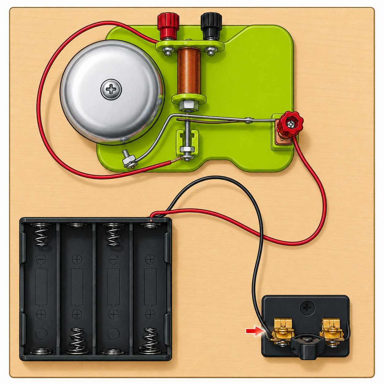
Step 5 - Battery Holder Black Wire → Knife Switch
- Take the black wire pre-installed on the battery holder.
- Connect it to one of the two metal terminals on the knife switch. In the reference images, this is the left terminal.
- Loosen the screw or clamp, insert the bare metal end of the wire, and retighten.
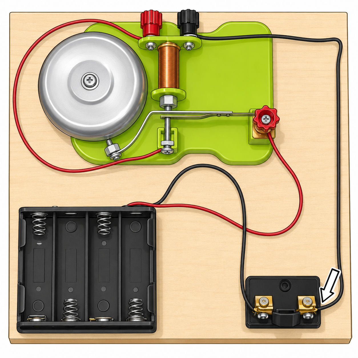
Step 6 - Black Binding Post → Knife Switch
- Take the second additional wire.
- Connect one end to the black binding post at the top of the bell.
- Route the wire toward the right side of the wooden base.
- Connect the other end to the free terminal of the knife switch. In the reference images, this is the right terminal.
- Tighten both connection points.
Step 7 - Verify the Circuit
The finished circuit should look like this:
| Wire | From | To |
|---|---|---|
| Red (pre-installed) | Battery holder | Red side terminal of the bell |
| Additional wire 1 | Red binding post | Bottom contact screw |
| Black (pre-installed) | Battery holder | Knife switch (terminal 1) |
| Additional wire 2 | Black binding post | Knife switch (terminal 2) |
Check that:
- No bare copper is exposed outside the terminals.
- All wires are firmly clamped.
- No wire touches the moving striker arm.
- The knife switch opens and closes freely.
- All components are secured to the base.
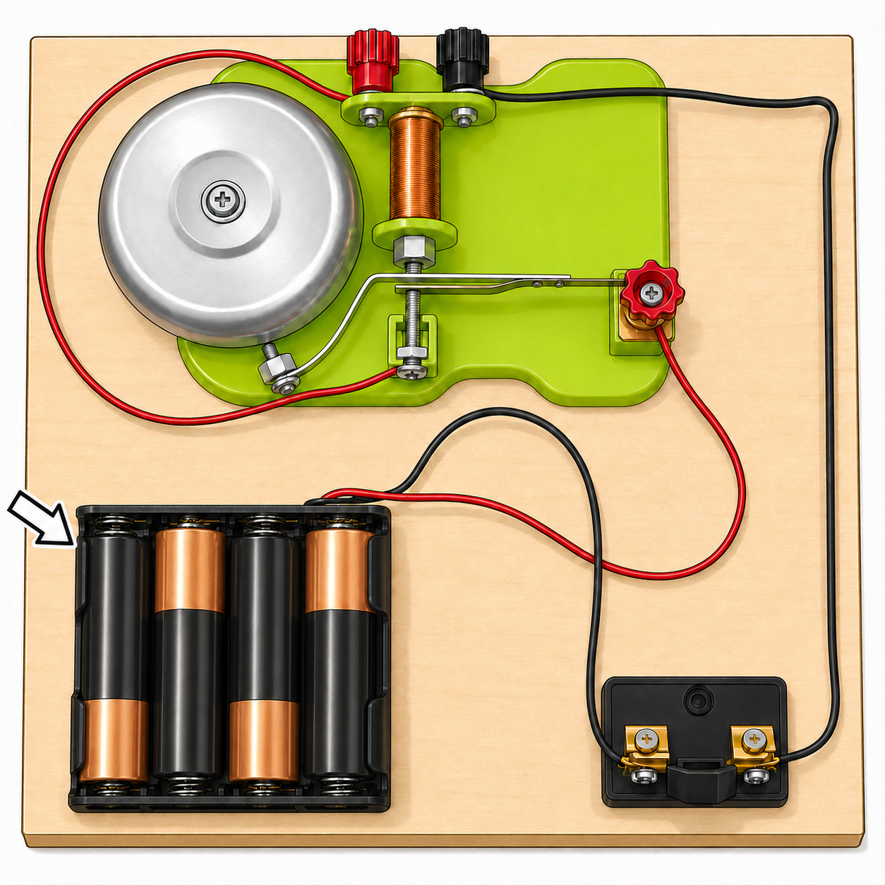
Step 8 - Install the Batteries
Keep the knife switch open before installing the batteries.
The 4 AA batteries are not included in the kit.
- Insert 4 AA batteries (1.5 V) into the battery holder.
- Follow the polarity markings in each compartment. The batteries must alternate direction:
- Battery 1: one direction
- Battery 2: opposite direction
- Battery 3: same as battery 1
- Battery 4: same as battery 2
Do not install all four batteries facing the same way. The kit will not work.
Step 9 - Test the Bell
- Double-check every connection one last time.
- Close the knife switch blade to complete the circuit.
- The electromagnetic coil will energize and the striker arm will hit the bell repeatedly.
- Open the knife switch to stop it.
What Is Happening?
Closing the knife switch completes a series circuit: battery → coil → contact → back to the battery. Current through the coil turns it into an electromagnet that attracts the iron striker arm, so the arm swings over and strikes the gong.
As the arm moves, it opens the bottom contact screw and breaks the circuit. With no current, the electromagnet loses its magnetism and a spring pulls the arm back, which closes the contact again and restarts the current. This self-interrupting "make-and-break" action repeats many times per second, so the bell rings as long as the switch is closed.
Troubleshooting
If the bell does not ring, check the following in order:
- Battery orientation. Confirm all four batteries alternate direction correctly.
- Battery charge. Try a fresh set of batteries.
- Knife switch. Confirm the blade makes solid contact when closed.
- Terminals. Retighten every connection point.
- Red wire path. The battery holder's red wire must go to the red side terminal of the bell.
- Black wire path. The battery holder's black wire must pass through the knife switch.
- Striker arm. Confirm nothing blocks its movement.
- Contact screw. If the arm does not vibrate, adjust the bottom contact screw slightly until the arm opens and closes the circuit correctly.
Safety
- Use only 4 AA batteries (1.5 V each). Never connect the kit to a wall outlet.
- Do not short-circuit the red and black wires against each other.
- Remove the batteries when the kit is not in use.
- Do not leave the knife switch closed for extended periods. The coil draws current continuously and will drain the batteries and heat up.
- Adult supervision is required when the kit is assembled by children.
If you do not have this kit, you can order it now. Check price and availability at the secure online store.
Secure Online Store
Order Now
Electric Bell Kit - Part# BELLKIT
Product URL:
https://shop.miniscience.com/BELLKIT
MiniScience.com
1059 Main Avenue
Clifton, New Jersey 07011
Tel: (973) 777-3113
Email: info@MiniScience.com